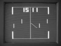
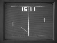
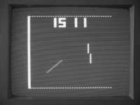
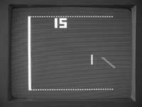
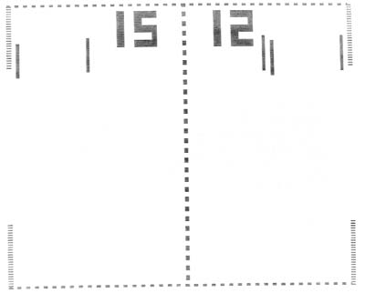
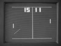
(Actual PAL version screenshots from an earlier version. New version has more accurate left/right edges.)
(Actual PAL version screenshots from an earlier version.
New version has more accurate left/right edges.)
70's TV game recreation using an Arduino (Atmel
ATmega328/168) processor.
(AY-3-8500 emulation - PAL or NTSC display, black and white version)
by Grant Searle
For news and updates, follow me on Twitter:Last update: 13th September 2013
WORK IN PROGRESS - REGULARLY UPDATED - PLEASE CHECK BACK IN A DAY OR TWO AND ENSURE YOU REFRESH YOUR BROWSER PAGE TO PICK UP LATEST VERSION. THE GAME IS FULLY WORKING BUT MAY BE TWEAKED SLIGHTLY. Thanks.
Index
Introduction
Specification
Differences between the 1976 and 1977
original games
Differences between the original PAL and
NTSC chips <== NEW 13th Sep 2013
Differences between this version and the original games
Redrawing the screen
Drawing the ball (smoothly)
Bat and ball intercept and trajectory
Sounds
The software
Source code and hex files
The hardware
How to play
Screenshots
My other pages
This project is to create a circuit that faithfully (as much as possible) emulates all 4 paddle games on the old TV game "pong" chip - the AY-3-8500. It uses an Atmel AVR processor - the ATmega328 (or ATmega168) as used on the Arduino UNO (etc) boards. It can either be created using individual components (very cheaply, with small part count) or can use an Arduino board with additional components attached.
The idea behind this project was to produce a 4 play game as accurate as possible to the originals.
I am an avid collector of the old consoles (see here) and have detailed knowledge as to the circuitry and functionality of the original arcade Pong (which I have also rebuilt).
I have seen other simple implementations of Pong on the Arduino, so I knew it should be possible to recreate.
The popular 4/6 game consoles normally used the AY-3-8500 (PAL version) or AY-3-8500-1 (NTSC version). I have several of the PAL versions so I was able to do an accurate side-by-side comparison of what I did with the original to ensure all games are as faithful as possible.
The NTSC version is currently based on datasheet information, but will be compared and updated to the actual AY-3-8500-1 chip when it arrives.
This works properly on new and old TVs via the A/V inputs.
NOTE: MY DIAGRAMS BELOW SHOW BLACK OBJECTS ON A WHITE BACKGROUND FOR CLARITY AND EASE OF READING THIS PAGE. IN REALITY, THE DISPLAY IS WHITE OBJECTS ON A BLACK BACKGROUND. ORIGINAL MANUALS ALSO TENDED TO ADOPT THIS WAY OF SHOWING SCREENS.
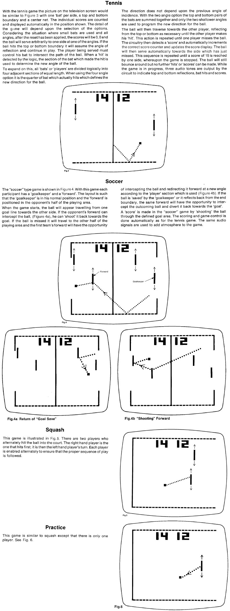
On the AY-3-8500, six games are possible : Tennis, Soccer, Squash and Solo, along with two shooting games.
I did not emulate the shooting games (although possible to do so) because additional gun hardware needs to be built/created and these will ONLY work with older CRT televisions. The gun picks up light flicker when focused on a bright area of the screen (ie. the target). The gun circuitry then registers a "hit" pulse if the trigger button is pressed while the light is detected. The new flat TVs don't produce the 50Hz flicker like the older CRT ones so no signal is available for the gun to pick up.
The original could switch between games without interrupting play - this is maintained in my emulated version.
Also implemented:
Bat sizes - small or large.
Angles - 20 degrees (easy) or 20/40 degrees (hard) and will deflect the ball
based on which part of the paddle is hit
Ball speed - slow or fast.
Reset button.
Automatic serve (no manual option at the moment, but can be added easily if
needed).
Game selection - instead of a multi-way switch, I decided to use a single
pushbutton to change games.
Attacking paddles allow pass-through with deflection.
The start point and direction of the ball (after reset) is the same as the original.
The ball speed and bat sizes can be changed instantly at any time, as on the original. The bat angles can also be changed any time and will be affected when a paddle is hit - again, same as the original.
The original playfield display consisted of 230 vertical lines (PAL). The clock was 2MHz, giving a pixel duration of 0.5uS. There are 73 or 79 pixels per line (see below).
The ATmega328 only has 2K of RAM, and a full bitmap of 230 x 80 (ie. 10 bytes per line) requires 2300 bytes so cannot fit.
The vertical resolution is therefore halved to 115 lines, each taking up 2 scan lines on the screen, restoring the original size. This does not affect the displayed field because the original objects on the screen occupy multiples of 2 lines. The paddles on the original chip would move in 2 line increments anyway, so that is the same here. Note: The ball is drawn at the FULL resolution of the full 230x80 ensuring a perfectly smooth movement (see below). The left and right edges require higher resolution and my code achieves this (see below).
Important differences between the original 1976 and 1977 game chips
In order to create an accurate reproduction, I carefully followed the datasheets and also took several photographs of the screen produced by the original chip.
What I need to point out here, though, is that I discovered a while ago that there are actually TWO versions of the AY-3-8500 PAL chip. The chip must have been partially redesigned in 1977 because the 1976 versions have the following differences.
1. The 1976 version of the playfield is wider - 79 pixels
instead of 73 on the 1977 version.
2. The 1976 bats are narrower than the 1977 version, even though the datasheet
states they are 0.5uS (1 pixel) wide.
3. The 1976 version has a smaller ball (3 lines high) than the 1977 version (5
lines high, and wider).
My photos of the screens (inverted colours) of the 1976 (left) and 1977 (right) versions of the original chip are shown here:

To see the differences in more detail, here are my actual screen photos (same scale) of the two versions merged on top of each other (showing all 5 bats on each):
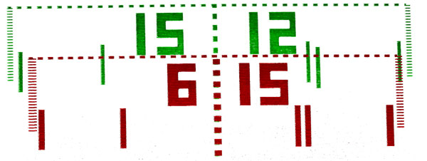
The 1976 chip display is shown in green and the 1977 one is shown in red. Both use the same 2MHz clock, so the pixels across the top and bottom of the window have the same placement.
In order to create a faithful reproduction, I either had to pick one version, or have a suitable option to switch between them. I did the latter, so what I present here can emulate either of the chips.
This therefore required some conditional code to be introduced to the drawing and incidence testing (ball hitting the bat or the wall). Additionally, the X-placement of the bats, scores and walls are no longer constant so needed to be put into variables that are set depending on the chip version chosen.
Important differences between the original PAL and NTSC chips
There are some differences which will be visible:
1. The scores on the NTSC version occupy 20 scanlines (4
lines per block) but the PAL version occupies 30 scanlines (6 lines per block) -
as on the datasheets.
The NTSC numbers are noticeably shorter.
2. The vertical net/centre line on the NTSC version is SOLID but the PAL version
is DOTTED (as can be seen on the diagrams above).
3. The NTSC picture has fewer scanlines, so a lower vertical resolution. This
results in the ball appearing to travel at slightly steeper angles on the NTSC
version because each step therefore has a larger Y displacement. Additionally,
this lower resolution makes the bats appear longer.
My recreation shown here FULLY implements the differences experienced on the two chips as shown below...

PAL on the left, NTSC on the right.
Differences between the original and emulated version
The original chips are NOT processors - they are combinational logic - gates/flip-flops within one chip. As a result, some signal paths go through more gates than others, so some of the signals are slightly stretched or delayed when compared to others. The ATmega version, however, has the same timing for all, so there is a small difference, but not noticeable unless you do a close side-by-side comparison of the screens produced.
Drawing the playfield
Due to the height of the playfield (taking up most of the screen) there is very little time left on each screen to do the processing, so I needed to try various methods to get everything redrawn in the few milliseconds that is available.
First option is to note the difference between the previous and new positions of the bats and the ball and clear any pixels no longer to be lit and then light the new ones as needed.
Second option is to completely clear the screen and re-draw everything each frame.
After trying both, the second option is actually better - the screen clear is very quick and ensures that all artefacts are cleared properly ensuring every screen is clean. There is sufficient time to do this between each frame.
Edge drawing
The edges of the screen are drawn internally as solid vertical lines.
The sides of the screen on the original chips are, however, dotted (every other line is blank) - this would require a vertical resolution of 230 pixels to do it. Each line occupies two scanlines so I was able to achieve the same effect by destructively modifying that line on the screen after one scan line was done so that the left and right pixels are cleared. So, when the second scanline is drawn for that same line the gap appears.
The screen is completely redrawn each frame so this destructive method works with no issue.
Drawing the ball (smooth movement)
The 2K limitation on the ATmega328 results in a limitation to the resolution available, so a 80x115 screen is reserved for the playfields.
115 vertical pixels with a pixel height of 2 lines per pixel gives a screen that is exactly the same as the originals.
However, to ensure the ball speed is exactly the same as the original results in some jitter when using this resolution as the ball normally works at twice the vertical resolution of 80x230 (note: same horizontal resolution, however) as is shown below...
A smooth ball traversal required a higher resolution. However, 2K bytes is not sufficient to support the required resolution for smooth ball movement. To achieve this, what is needed is for the screen resolution to remain at 80x115 for the main part of the screen but switch to double the resolution for the area occupied by the ball. This is what I did. I created an additional 5 line screen which would be displayed at 1 line per pixel instead of 2 lines per pixel, and this would be dynamically positioned up or down the screen to enclose the ball. This way, it was then possible to create the ball of the correct height - 3 or 5 lines depending on whether the 1976 or 1977 chip is being emulated.
During each screen refresh, the ball routine copies a section of the low res screen into the high res screen then draws the ball in there. The display render code is then switched between the two lines per pixel main field to the 1 line per pixel ball area then switched back to complete the screen. This is illustrated in the following diagram:
This implementation now produces a perfectly smooth ball movement, faithfully recreating the original.
As in the original, the angle of bounce or deflection
depends on which part of the bat is hit. The angle option switch defines if ball
angles are restricted to two angles (+/-20 degrees) or whether there are 4
possible angles (+/- 20 degrees and +/- 40 degrees).
The bat is divided into four segments which define which of the angles the ball
will leave.
The bat will either bounce the ball if the ball is travelling towards the player
or deflect the ball if it is travelling away from the player.
The diagram below illustrates this behaviour:
The ball speed (x and y increments) match the original specifications, and are shown below:
The original produced 500Hz beeps when hitting the walls, 1KHz beeps when hitting the bats and 2KHz beeps when scoring. This has been faithfully reproduced. The connection diagram below shows the output going to a line-out socket, but will readily drive a small sounder.
The video display driver is a cut-down TV Out library (with sound), so full credit for this goes to the original author. The code for this is attached to the end of my game code because I needed to modify the existing library specific for this game. All code can be maintained in one place. I have modified it as I needed my own screen resolution to match the original chips. All code not relevant has been removed. I have also renamed the methods to match my naming convention. Comments have been removed (most methods are self-explanatory based on the name) but the original library can be obtained here if you require more details.
As mentioned above, the playfield that is being displayed is either 73x115 or 79x115 pixels. The TV Out library requires the x dimension to be divisible by 8, so a suitable size is 80x115 pixels for both versions. I wrote an updated display line handler to display the pixels at the correct width needed to match the original. Additionally, I updated the renderer to auto-switch resolutions when drawing the ball area, as mentioned above.
The ball y-coordinate has been scaled by a factor of 2 so that the speed matches the original. So, in the code there is a virtual y coordinate and the actual ball y coordinate. The double-resolution screen allows the ball to be positioned at a required vertical resolution of twice the rest of the screen.
All coordinates have the (0,0) origin being the top-left corner of the displayable playfield.
A summary of each of the methods used in my code is shown below. Please refer to the actual code for more detail.
setup
Standard Arduino entry point.
Sets the analogue and switch input pins
Call the reset method to initialise defaults.
Initialise and start the video display
reset
Resets the score, ball position, and ball velocities ready to start a game.
The squash player is reset to 1.
Attract mode is turned off.
loop
Standard Arduino program run loop, after setup is complete.
This is the main gameplay loop and is synchronised to run once per frame.
Wait for synchronisation
Check the chip version pin to set the appropriate sizes and positions of the
playfield and all displayable objects. (configureSelectedChipVersion method)
Clear the screen
Set the game (setGame method)
Draw the scores (drawScores method)
Draw the game boundary (drawBoundary method)
Configure the running game (setGameOptionsFromSwitches method)
Draw all paddles that are needed for the current game (drawPaddles method)
Check if the reset switch is pressed, if so, reset the score and come out of the
loop now
Move the ball to the new position (new pos=old pos + velocity step)
If the new position of the ball touches a wall then beep and swap the velocity
direction to make it bounce
If the new position of the ball touches the left or right edge of the playfield
then:
if the ball is visible then
a score is incremented if no player has yet
reached 15
a beep is sounded
the ball is repositioned HORIZONTALLY to be
1/3 of the playfield in from where it touched the edge. This gives a short time
before it comes back in to play.
the ball is made invisible
if 15 is reached then gameplay is over
(switches to attract mode)
if the ball is invisible then
it is made visible
If the ball is visible then draw the ball (drawBall method)
setGameOptionsFromSwitches
Read the ball speed switch and adjust the ball velocity if needed
Read the angles switch and assign the angles flag ready for the next bat hit
Read the paddle height switch and assign the paddle height variable to the
required size
drawPaddles
Read the paddles
Convert the paddle value to vertical screen coordinates
Draw the paddles (drawPaddle method) - two for tennis and squash, four for
soccer and one for solo. This routine will also check if the ball is in contact
and make it bounce/deflect as needed.
configureSelectedChipVersion
Read the version selection line and set the position, width and field size
variables to match.
drawPaddle
The passed paddle number (1..5) will determine the x coordinate to use. The
passed paddle value determines the y value.
Draw the paddle
If the ball is visible and not in attract mode then a check is done to see if
the ball is touching the current paddle.
If it is touching then
beep
if the paddle is a defending paddle (based on paddle
number and ball direction) then reverse the x velocity to make it bounce.
if the paddle is an attacking paddle (ie facing the
same way as the ball travel) then the x velocity is not changed, allowing it to
pass through (being deflected as needed)
the y velocity (direction) depends on where the paddle
was hit and may be one of 2 (up/down) or 4 (two speed up, two speed down)
velocities
drawBall
Copy the ball part of the playfield to the double resolution area.
Set either 3 pixels (1x3) on the 1976 version or 10 pixels (2x5) on the 1977 version at the ball x/y
location on the double resolution screen area.
setBallPixel
Used by the drawBall method to set a pixel on the double resolution area.
drawDigit
Draw a bitmap of a digit specified at the location parameters
drawScores
Draw each score digit by calling the drawDigit method. Don't draw the 10's digit
if score is less than 10
drawBoundary
Draw the top and bottom lines
Draw the goal walls if soccer selected (game 2)
Draw a solid wall on the left if squash or solo selected (game 3 and 4)
Draw a dotted line down the middle of the field if tennis or soccer selected
(game 1 and 2)
setGame
Check if the game select button has been pressed for 4 consecutive frames (80mS)
to eliminate contact bounce.
If so, set the game number to the next game
other
I have defined the required bitmaps for the 7 segment digits and are stored in
program memory.
The Arduino source code (sketch) plus a hex file (for programming directly) is HERE.
Update 30th Jul 2013: Change the
"version select" from PB5, ATmega pin 19 to PB4, ATmega pin 18 to avoid LED boot
flash conflict if using the Arduino bootloader. Ensure you follow the updated
schematic or pinout (below).
Update 25th August 2013: PAL/NTSC selection, plus faster drawing of the
borders and centre line, needed for the faster NTSC timings.
You do not need Ardhuino software or hardware/bootloader
- you can program the ATmega328 directly using the HEX file if you have a
suitable programmer. You can also compile the code for an ATmega168 as it is
small enough to fit.
If programming using the HEX file manually, ensure the programmer will set the
correct chip configuration - XT clock, divide by 1, no clock out.
Here is a diagram showing the ATMEL and ARDUINO pin designations for the ATMEGA328. Also shown is the pin function as used within this project.
Update 30th Jul 2013: Pinout and schematic - change the "version select" from PB5, ATmega pin 19 to PB4, ATmega pin 18 to avoid LED boot flash conflict if using the Arduino bootloader. Ensure you have the latest code (above). Additionally, potentiometers turned around so that clockwise = up, anticlockwise = down, as on original consoles.

Pins that do not have a game pin designation are to be left unconnected.
Complete wiring required for this game is shown here:
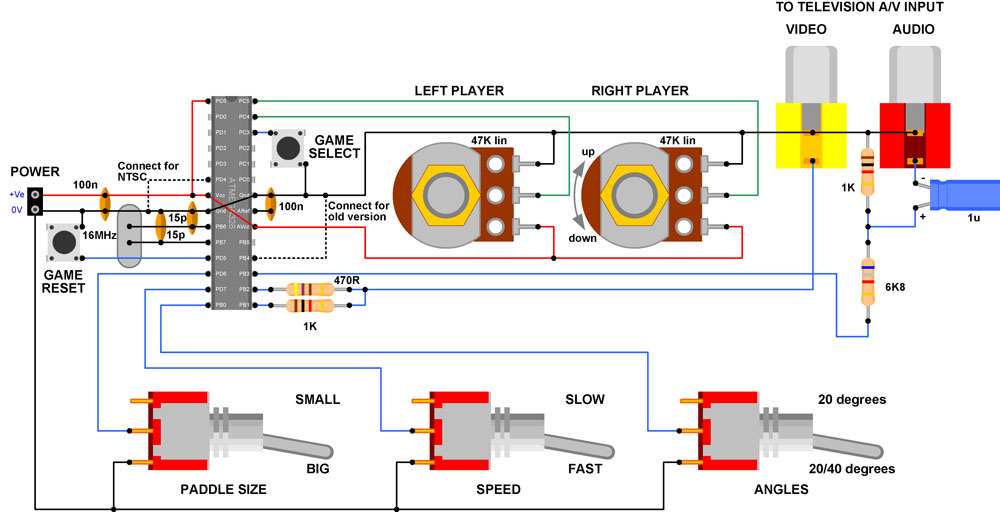
The audio components are set for a standard line-input. However, these can be replaced with whatever is required to produce the sound for example a peizo sounder or speaker in series with a 100R resistor.
The potentiometers shown are 47K, but can be anything between 10K and 100K or more. Larger values will result in a lower current drain.
All switch inputs are pulled high with internal resistors, so only need to switch to ground.
The power can be anything from about 3V to 5V, so will run off 2 or 3 AA batteries, as an example.
The dotted connection will switch the chip to emulate the 1976 (wider) version. This can be wired, ignored or connected to a switch.
The switches are optional, and the required pins can either be left open or tied to ground if that functionality change is not needed.
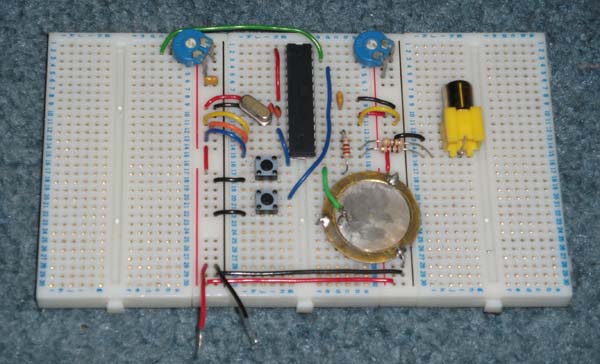
Below is a prototype/test construction. This is using a peizo element in series with a 220R resistor as the sounder. The two buttons are reset and game selection. As you can see very few components are needed to make a complete game.
If you are familiar with the original 70's games then you already know - gameplay here is identical.
If you are not, then here are a couple of scans from the General Instruments "GIMINI" datasheets showing the principles involved...
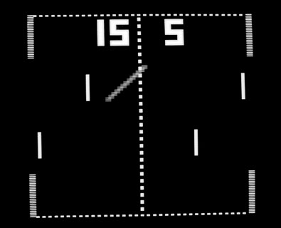
Here are screenshots of my ATmega / Arduino PAL version running on a PAL monitor. The diagonal streak is the ball path during exposure.
Chip mode set to new (1977) version:
Chip mode set to old (1976) version:

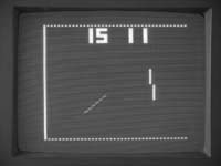
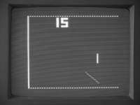
Patterning is not visible on-screen - it is merely due to the scan lines and is a common artefact when resizing TV images on a computer.
These are actual screenshots from an earlier version. New version has more accurate left/right edges as described above. Picture to be updated soon.
PLEASE CLICK HERE TO GO TO MY MAIN PAGE WHERE YOU WILL FIND SEVERAL MORE PROJECTS
I hope this page has been useful.
Grant.
To contact me, my current eMail address can be found here. Please note that this address may change to avoid spam.
Note: All information shown here is supplied "as is" with no warranty whatsoever, however, please let me know if there are any errors. All copyrights recognised.